Transparent insulation
Contents |
[edit] Introduction
Honeycomb transparent insulation was first developed in the 1960s to enhance the insulation value of glazing systems with minimal loss to light transmission (Hollands 1965). Over the past 25 years, transparent insulation materials (TIMs) have been applied to windows, walls, skylights, roofs and high-performance solar collectors (Dolley et al. 1994, Kaushika and Sumathy 2003).
Transparent insulation materials perform a similar function to opaque insulation, but they have the ability to transmit daylight and solar energy, reducing the need for artificial light and heating. They transmit heat, mainly through conduction and radiation, but convection is usually suppressed (Kaushika and Sumathy 2003).
The thermal and optical properties of transparent insulation materials depend on the material, its structure, thickness, quality and uniformity. They typically consist of either glass or plastic arranged in a honeycomb, capillary or closed cell construction. Alternatively, granular or monolithic silica aerogel can be used to achieve higher insulation values.
Depending on the structure of the material, its arrangement can be classified as:
- Absorber perpendicular.
- Absorber parallel.
- Cavity.
- Quasi-homogeneous.
Figure 1: Types of transparent insulation
Figure 2 (below) compares the thermal conductivity of various transparent insulation materials and other insulation products. Okalux Glass Honeycomb is a commercially produced absorber perpendicular TIM with a thermal conductivity of 0.039W/m.K (Platzer et al. 2004).
Translucent silica aerogel, a quasi-homogenous TIM, has the lowest thermal conductance of any known solid at 0.004-0.018W/m.K (Yokogawa 2005, Cabot 2009). Only vacuum technology is comparable with thermal conductivities in the region of 0.005W/m.K (Zimmerman et al. 2001).
Figure 2 - Thermal conductivities of insulation materials
[edit] Transparent insulation in glazing
TIM glazing typically consists of glass or plastic capillaries or honeycomb structures sandwiched between two glass panes. These systems diffuse light well, while reducing glare and shadowing (Lien et al. 1997). Commercial products such as Okalux and Arel glazing can exhibit low U-values with good solar and light transmittance.
According to Hutchins and Platzer (1996), 40-mm-thick Okalux capillary glazing, and 50-mm-thick Arel honeycomb glazing can achieve U-values of 1.36 W/m2K, comparable to modern gas filled double glazing. Alternatively, 80 and 100mm thick systems can achieve U-values of 0.8 W/m2 K, respectively, comparable to modern gas filled triple glazing units.
According to Robinson and Hutchins (1994), the application of TIM glazing tends to be limited to skylights, atriums and commercial/industrial facades as the geometric structure of TIMs tends to restrict a clear view to the outside. Transparent insulation materials appear most transparent when viewed front on and tend to be opaque when viewed at an angle. In order to increase the visible transmission of TIM glazing, it is important to increase capillary size, reduce the thickness, or view the transparent insulation material from a distance (Lien et al. 1997).
According to measurements by Hutchins and Platzer (1996), normal light transmittance through honeycomb and capillary TIM glazing is 78 and 84%, respectively. By comparison, normal light transmission through standard double glazing is similar at 81%. Low-emissivity gas filled double and triple glazing units can be lower at 66 and 63%, respectively (Hutchins and Platzer 1996).
Platzer and Goetzberger (2004) and Wong et al. (2007) claim that commercial uptake of transparent insulation materials has been slow due to perceived high-investment costs and the limited number of payback studies that have been carried out. Peuportier et al. (2000) suggest that production quality must improve to reduce imperfections such as rough or melted edges, which can hinder clarity.
Kaushika and Sumathy (2003) suggest that considerable progress has been made to reduce the cost of manufacturing transparent insulation. On the basis of this lower cost, Wong et al. (2007), calculated a 3–4-year payback period for an industrial production facility in Salzgitter, Germany, renovated with 7,500m2 of TIM glazing. It is unclear whether these payback periods can be directly translated to the domestic or commercial sector, but nonetheless, this payback period is significantly less than new double glazing.
Research into TIM glazing focuses on developing systems using transparent silica aerogel. This lightweight, nanoporous material has an excellent combination of high solar and light transmittance and low thermal conductance (Schultz and Jenson 2008).
According to Bahaj et al. (2008), aerogel glazing is often portrayed as the ‘holy grail’ of future windows, offering the potential to achieve U-values as low as 0.1 W/m2 K, as well as high-solar energy and daylight transmittance of approximately 90% (Bahaj et al. 2008, Schultz and Jenson 2008).
The thermal, optical and infrared properties of silica aerogels are well known. The material effectively transmits solar light while blocking heat transfer by conduction, convection and thermal infrared radiation. Silica aerogel has the lowest thermal conductivity of any material, ranging from 0.018 W/mK for granular silica aerogel to 0.004 W/mK for evacuated monolithic silica aerogel (Yokogawa 2005, Cabot 2009).
To date, several small-scale prototypes have been constructed to characterise the performance of monolithic silica aerogel in glazing. Samples are sandwiched between glass sheets and evacuated to protect the aerogel from tension and moisture, as most aerogels are brittle and hydrophilic meaning that they will degrade in contact with water (Zhu et al. 2007, Schultz and Jenson 2008).
Duer and Svendsen (1998) measured the performance of five different monolithic aerogel slabs, produced in different laboratories, ranging in thickness from 7 to 12 mm. Centre pane U-values of glazed samples ranged from 0.41 to 0.47 W/m2 K. Solar and visual transmittance ranged from 74 to 78% and from 71 to 73%, respectively.
Jensen et al. (2004), Schultz et al. (2005) and Schultz and Jenson (2008) reported on the performance of monolithic aerogel glazing produced by the Airglass AB plant in Sweden. The largest prototype was a 1.2m2 window, consisting of four 55 cm × 55 cm × 15mm monolithic tiles fitted into an evacuated, sealed framing unit. This prototype achieved a centre pane U-value of 0.66 W/m2K (measured in a laboratory), and an overall U-value of 0.72W/m2K (measured using a hot box), indicating that the effect of thermal bridging at the edges was small. The direct solar transmittance was 75–76% and the normal transmittance in the visible spectrum was 85–90%.
Despite its impressive combination of thermal and optical properties, monolithic silica aerogel is yet to penetrate the commercial glazing market. According to Rubin and Lampert (1983), the cost, long processing time of aerogel, difficulty in manufacturing uniform samples and lack of adequate protection from tension and moisture are key barriers hindering progress. Duer and Svendsen (1998) and Bahaj et al. (2008) suggest that further work is required to improve the clarity of samples if they are to replace conventional windows.
A key issue is that the nanostructure of silica aerogel scatters transmitted light, resulting in a hazy view. Schultz and Jenson (2008) claim that through improved heat treatment techniques, the Airglass AB plant is capable of producing aerogel tiles with parallel and smooth surfaces, resulting in undistorted views when shielded from direct solar radiation. However, when exposed to non-perpendicular solar radiation, visual distortion still occurs. According to Jensen et al. (2004), Schultz et al. (2005) and Schultz and Jenson (2008), aerogel glazing is an excellent option for large areas of north-facing facades, enabling a net energy gain during the heating season. Through developments in edge sealing techniques, units are anticipated to have a lifespan of 20–25 years without degradation (Schultz and Jenson 2008).
The use of granular aerogel in glazing offers an alternative solution to monolithic aerogel which is cheaper, more robust and easier to produce on a commercial scale. Systems should not be considered as a direct replacement for transparent windows, because the granules restrict the clear view to the outside. Instead, this material offers the potential to achieve low U-values, enhance light scattering and drastically reduce sound transmission in areas where an outside view is not essential (Wittwer 1992).
The performance of granular aerogel glazing was originally investigated by Wittwer (1992). U-values from 1.1 to 1.3W/m2K were measured for 20-mm-thick glazing units filled with granules ranging from 1 to 9mm in diameter. Smaller granules perform better thermally, as less heat is conducted through air gaps between granules. Optically, the larger aerogel granules permitted more light and solar transmission.
More recently, Reim et al. (2002, 2005) have measured and modelled the performance of granular aerogels encapsulated in a 10mm twin-wall plastic sheet sandwiched between two glass panes with an insulated gas filling. The twin-wall sheet was selected to prevent granules from settling over time, creating a thermal bridge along the top edge. U-values as low as 0.37–0.56W/m2 K were calculated for prototypes containing krypton/argon gas fillings. Without the glass cover panes, the solar and light transmission was 88 and 85%, respectively.
Using a thermal model in a German climate, Reim et al. (2002) calculated the energetic benefit of granular aerogel glazing to be comparable to triple glazing. Results demonstrated that granular aerogel glazing could reduce the risk of overheating on southern and east/west facades. On north-facing facades, the energetic balance of aerogel glazing was significantly better than triple glazing due to improved heat retention.
[edit] Transparent insulation in flat plate solar collectors
The most throughly documented application of transparent insulation materials is in flat plate solar collectors (Kaushika and Sumathy 2003, Wong et al 2007). These systems are designed to heat air or water when irradiated by the sun. Basic components are a south facing TIM cover, which transmits solar energy whilst reducing convection and radiation losses to the atmosphere, and a black solar absorbing surface to transfer absorbed energy to a fluid (Duffie and Beckman 2006).
Experimentation by Rommel and Wagner (1992) has shown that flat plate collectors containing 50-100mm polycarbonate honeycomb layers function well, facilitating working temperatures between 40-80C. Higher working temperatures up to 260C can be achieved using glass honeycombs, since plastic covers are susceptible to melting at temperatures above 120C (Rommel and Wagner 1992).
Nordgaard and Beckman (1992) modelled the performance of flat plate collectors containing monolithic silica aerogel. It was shown that the reduction in solar transmittance compared to a single glass pane is more than compensated by the reduction in heat losses. Svendsen (1992) demonstrated that a 1.4m2 prototype containing evacuated monolithic silica aerogel was twice as efficient as commercial high temperature flat plate collectors.
[edit] Transparent insulation in passive solar walls
When retrofitted to south facing external walls, transparent insulation materials with an air gap behind can be used to capture solar energy. This energy can be used iether by venting the warm air inside, or by allowing the heat to conduct passively through the wall. According to Caps and Fricke (1989), Athienitis and Ramadan (1999), and Suehrcke et al. (2004), transparent insulation materials including glass honeycombs, flat/corrugated polycarbonate sheets and evacuated silica aerogel can provide significant energy savings when retrofitted to residential and commercial opaque walls. Results suggest that on cold sunny days, no additional heating may be required, yet control strategies are necessary in summertime to minimise overheating.
Dolley et al. (1994) used a test cell to monitor performance of a polycarbonate honeycomb TIM system. The results were extrapolated to assess how the TIM would perform when retrofitted to typical UK dwellings built to different construction standards. 8m2 of transparent insulation material was predicted to save approximately 40kWh/m2/year on super insulated homes and 140kWh/m2/year on a pre-1930’s property with solid walls. In a comparative analysis of a flat plate solar air collector and an opaque wall clad with polycarbonate TIM, Peuportier and Michel (1995) demonstrated an increase in the efficiency of these systems compared to conventional single glass pane systems by 25% and 50% respectively.
[edit] Overheating
Dolley et al. (1994) measured the in-situ performance of opaque walls clad with transparent insulation. Results were extrapolated to show how transparent insulation materials would perform when retrofitted to typical UK dwellings built to different construction standards. It was predicted that 8m2 of TIM could save approximately 40kWh/m2/year when retrofitted to super insulated homes and 140kWh/m2/year when retrofitted to a pre-1930’s property with solid walls. Without shading, the hours of overheating (above 27C) were raised from 4 to 31 for properties with solid walls, and from 320 to 784 for super insulated homes.
This article is based on a paper written by Mark Dowson of --Buro Happold. An online version of Mark's EngD thesis can be downloaded at the Brunel University website: http://bura.brunel.ac.uk/bitstream/2438/7075/3/FulltextThesis.pdf
[edit] Related articles on Designing Buildings
Featured articles and news
Gregor Harvie argues that AI is state-sanctioned theft of IP.
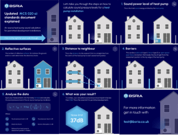
Heat pump and wind turbine sound calculations for PDRs
MCS publish updated sound calculation standards for permitted development installations.
Homes England creates largest housing-led site in the North
Successful, 34 hectare land acquisition with the residential allocation now completed.
Scottish apprenticeship training proposals
General support although better accountability and transparency is sought.
The history of building regulations
A story of belated action in response to crisis.
Moisture, fire safety and emerging trends in living walls
How wet is your wall?
Current policy explained and newly published consultation by the UK and Welsh Governments.
British architecture 1919–39. Book review.
Conservation of listed prefabs in Moseley.
Energy industry calls for urgent reform.
Heritage staff wellbeing at work survey.
A five minute introduction.
50th Golden anniversary ECA Edmundson apprentice award
Showcasing the very best electrotechnical and engineering services for half a century.
Welsh government consults on HRBs and reg changes
Seeking feedback on a new regulatory regime and a broad range of issues.
CIOB Client Guide (2nd edition) March 2025
Free download covering statutory dutyholder roles under the Building Safety Act and much more.
Minister quizzed, as responsibility transfers to MHCLG and BSR publishes new building control guidance.
UK environmental regulations reform 2025
Amid wider new approaches to ensure regulators and regulation support growth.









Comments
This really provides a concise overview of transparent insulation materials and their properties. The breakdown of the different types, like aerogels and suspended microspheres, is helpful for understanding their variations.
The applications section mentions the potential for transparent insulation in building facades. Are there any specific considerations for using transparent insulation in building envelopes, such as integration with existing window systems or thermal performance requirements in different climates?
Thanks for your comment. Why don't you create a company profile, write an article and associate the article to your company. A better way to gain free publicity and share your knowledge on Stucco at the same time!